Home Studio

Hier mal ein kleiner Einblick in die Planung und Umsetzung meiner Home Studio Einrichtung in den letzten Jahren.

Studiotisch

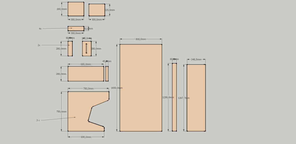
Begonnen hat es mit dem Bau meines Studiotisches, welcher groß genug für damals zwei Bildschirme (23″ und 24″) und einem Paar KRK Rokit RP5 G3 White Noise Limited Edition war. Die Nahfeldmonitore stehen dabei auf kleinen Podesten, damit eine optimale Hörposition erreicht werden kann. In den Podesten finden mein Golden Age Microphone Pre-Amp und das Soundinterface Platz. Nachdem ich dann auf die Yamaha HS8 umgestiegen bin (klingen echt mächtig, nach dem Einmessen sogar noch deutlich besser) mussten die zwei Bildschirme einem 27″ WQHD mit 10bit Farbansteuerung (voller Adobe RGB Farbraum) weichen, mit welchem ich immer noch zufrieden bin (sämtliche Druckvorbereitung, wie Albumcover und Booklet, lassen sich fast ohne Probedruck erledigen, das ist aber ein anderes Thema).
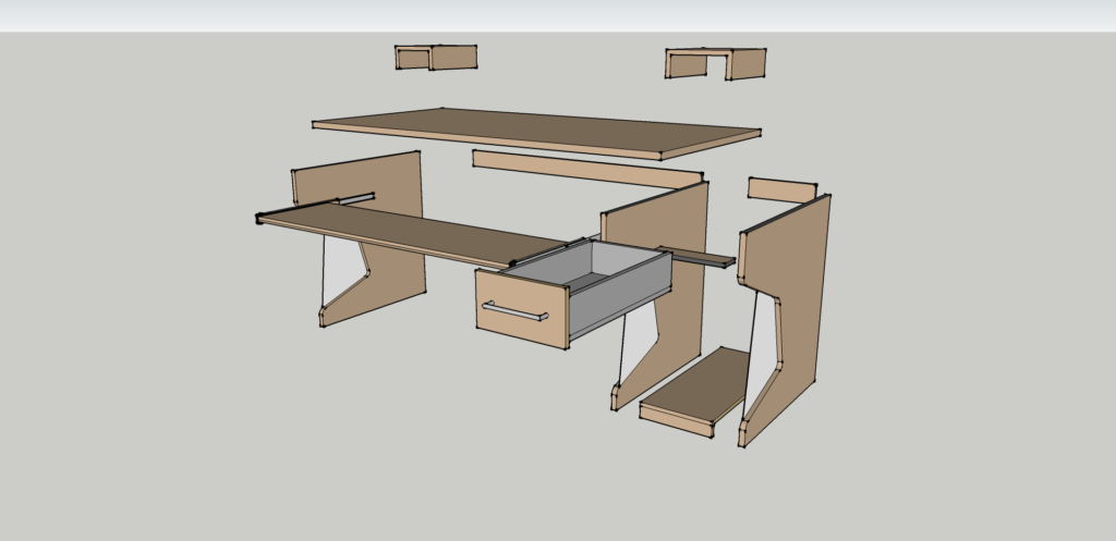
Google Sketchup Konzept
Einzelteile

Raumakustik

Ein wichtiger Punkt ist die Raumakustik. Prinzipiell unterscheidet man zwischen Diffusoren und Absorbern. Erstere zerstreuen einfallende Schallwellen in unterschiedliche Richtungen und verteilen so die Schallwellen gleichmäßiger im Raum. Das funktioniert vor allem bei Mitten und Höhen. Absorber hingegen „schlucken“ einfallende Schallwellen, in dem sie diese sehr oft brechen und dabei der Schallwelle Energie entziehen. Am besten eignen sich daher poröse Materialien wie Schaumstoff oder Glas-/Stein-/Holzwolle. Absorber gibt es für verschieden Frequenzbereiche, generell gilt, je tiefer die Frequenz, desto dicker sollte der Absorber sein. Ein Abstand des Absorbers zur Reflektionsfläche (Wand oder Decke) kann ebenfalls die Absorptionseigenschaften beeinflussen.

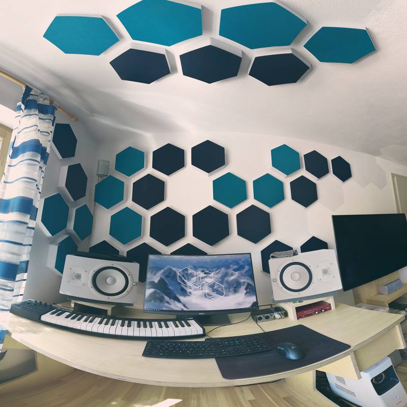
Da mein Home Studio eigentlich mehr als Wohnzimmer genutzt wird, gibt es ein paar Einschränkungen was die Platzierung der Schallquelle (Nahfeldmonitore) als auch die möglichen Akustikmaßnahmen angeht. Eine symmetrisch im Raum platzierte Schallquelle und dicke Bassabsorber in den Ecken fallen dabei schonmal weg. Ich beschränke mich also darauf, die schlimmsten Raumfehler zu korrigieren: Flatterechos, welche man sogar auf den Vocal-Aufnahmen heraushören konnte, und die generelle Nachhallzeit. Weitere Optimierung mache ich dann durch das Einmessen und EQing der Monitorboxen.
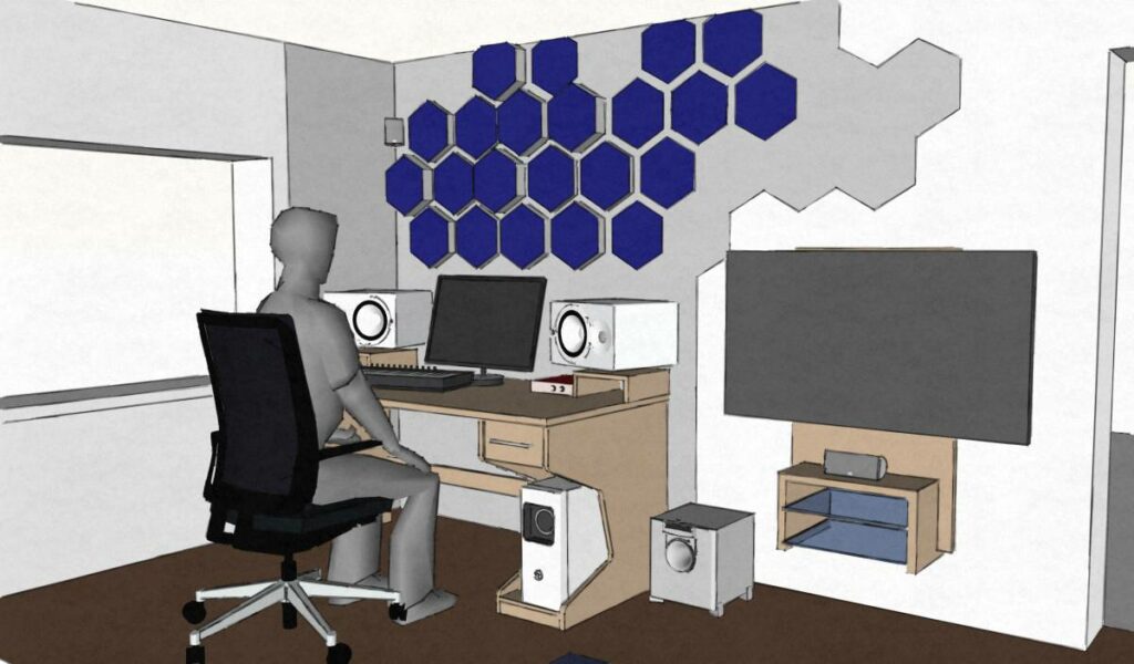
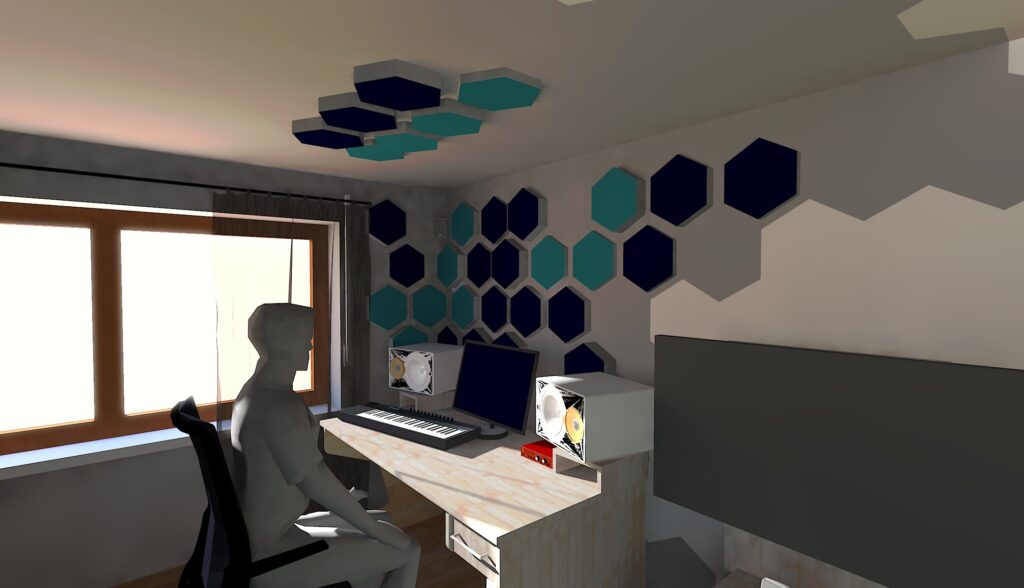
Erstes Konzept der Raumakustik in Google Sketchup
Zweiter Versuch in Google Sketchup (Twilight Renderer)
Leider sind ein paar Flächen nicht richtig gerendert, hatte aber keine Lust das zu beheben

Schlussendlich habe ich mich für 42 Basotect® (spezieller Akustikschaum) Hexagone (35, 55 und 75 mm dick) entschieden, welche ich wie in den Konzeptbildern vor allem an den ersten Reflektionspunkten installiert habe. Dickere Platten kamen dabei in die Ecken (Bassabsorber); ein wenig graue Farbe (angepasst an das Basotect® grau) rundet die Baumaßnahme ab.
Messergebnisse

Und was hat das nun gebracht? Um diese Frage zu beantworten kann man das kostenlose Tool Room Acoustics Software REW verwenden, welches bei mir von einem Behringer ECM-8000 Messmikrofon gespeist wird. Für den Akustikvergleich wurden 9 Punkte (einmal zentral am optimalen Abhörplatz im gleichseitigen Dreieck mit den beiden Monitorboxen und mit 20 – 30 cm Abstand im Quadrat darum herum) pro Lautsprecherseite einzeln vermessen. Der Durchschnitt aller Messungen mit einer frequenzabhängigen Glättung (smoothed var) zur besseren Visualisierung ist im Folgenden dargestellt:
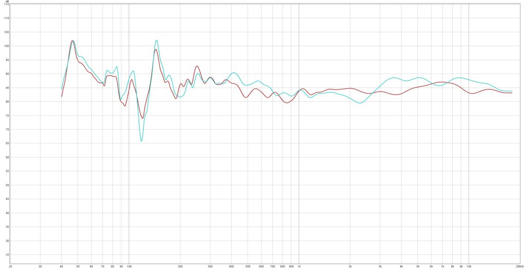
Vor (türkis) und nach der Verbesserung der Raumakustik (rot)

Deutlich zu sehen sind die Verbesserungen bei den mittleren und hohen Frequenzen (2k – 10k Hz), welche nun gleichmäßiger wiedergegeben werden. Ebenso ist eine leichte Verbesserung im Bassbereich zwischen 100 – 200 Hz erkennbar. Alle weiteren Frequenzanpassungen leistet die vom REW Tool generierte EQ Einstellung, welche für Windows Sounds (Spotify, Youtube, Games, …) mit Equalizer APO und für die DAW (in meinem Fall Studio One) mit einem parametrischen EQ angewandt wird.

Auch bei den Nachhallzeiten sind Verbesserungen vor allem im mittel- und hochfrequenten Spektrum erkennbar. Messtechnisch stellen diese Ergebnisse bei weitem nicht das Optimum dar, die Veränderung ist aber deutlich zu hören. Der Raum klingt nun ein gutes Stück trockener als vor den Akustikverbesserungsmaßnahmen.

Nachhallzeiten der einzelnen Frequenzen vor den Akustikmaßnahmen
Nachhallzeiten der einzelnen Frequenzen nach den Akustikmaßnahmen

Wer auch ohne Raumoptimierung einen möglichst linearen Sound genießen will, sollte sich mal das AutoEQ Projekt von jaakkopasanen in GitHub angucken. Dort findet man bereits eine lange Liste an EQ Einstellungen für über 2500 Kopfhörer. Mein so optimierter Beyerdynamics Custom Studio rundet das Home Studio Setup ab.

EV Green Charging

Who has not dreamt of an automated EV charging control to use exactly the amount of energy that is produced by the rooftop PV system and not consumed by the household devices? Here is a short summary on how I built my solution using Home Assistant, an ESP32 for smart metering and a Keba wallbox. This blog entry will provide an overview about the work done without going too much into technical details. If you want to reproduce a similar solution, I advise you to follow the reference links.

Smart Metering with an ESP32

Some time ago, the energy meters for both the PV system and the household were exchanged to Logarex LK13BE8030x9. A short Google search points to the manual (German only) hosted by Stadtwerke Burgdorf. The manual unveils an unidirectional extended data mode on the optical connection. To enable this extended data mode (more detailed data including current and voltage on each phase), a PIN request from the metering point operator (in this case Bayernwerk Netz GmbH) was required, which worked flawlessly via a short phone call. The extended data contains the following data set: Some starting bytes, several key-value pairs (OBIS numbers) and final bytes. The data is sent (pushed) from the smart meter every 3-4 seconds (!), which provides a near real-time update of current state of the energy system on all three phases.

Extended data set from the Logarex smart meter
/LOG5LK13BE803049
<ACK>050
<STX>
1-0:96.1.0*255(001LOG0064800017)
1-0:1.8.0*255(000000.4392*kWh)
1-0:1.8.1*255(000000.0000*kWh)
1-0:1.8.2*255(000000.4392*kWh)
1-0:2.8.0*255(000000.8322*kWh)
1-0:16.7.0*255(000000*W)
1-0:32.7.0*255(000.0*V)
1-0:52.7.0*255(000.0*V)
1-0:72.7.0*255(229.9*V)
1-0:31.7.0*255(000.00*A)
1-0:51.7.0*255(000.00*A)
1-0:71.7.0*255(000.03*A)
1-0:81.7.1*255(000*deg)
1-0:81.7.2*255(000*deg)
1-0:81.7.4*255(000*deg)
1-0:81.7.15*255(000*deg)
1-0:81.7.26*255(000*deg)
1-0:14.7.0*255(49.9*Hz)
1-0:1.8.0*96(00000.0*kWh)
1-0:1.8.0*97(00000.0*kWh)
1-0:1.8.0*98(00000.0*kWh)
1-0:1.8.0*99(00000.0*kWh)
1-0:1.8.0*100(00000.4*kWh)
1-0:0.2.0*255(ver.03,EF8C,20170504)
1-0:96.90.2*255(0C69)
1-0:97.97.0*255(00000000)
!
<ETX>
<BCC=0x63>
<BCC=0x63>

After testing around with an ESP8266 and coding a prototype based on Arduino and the experience from msxfaq.de (very helpful documentation about the D0 connection and SML), I noticed that one ESP8266 core for two smart meters connected via software UART and additional WiFi connection pushing the decoded values to a MQTT server did not provide sufficient reliability. Thus, an ESP32, which has three built-in hardware UART controllers and two processing cores (one for WiFi, the other one for the Arduino program), provided a solid solution. The final IR sensor (only receiving part, as the Logarex meter does only support unidirectional communication on optical connection so far) is based on the one engineered by volkszaehler.org.

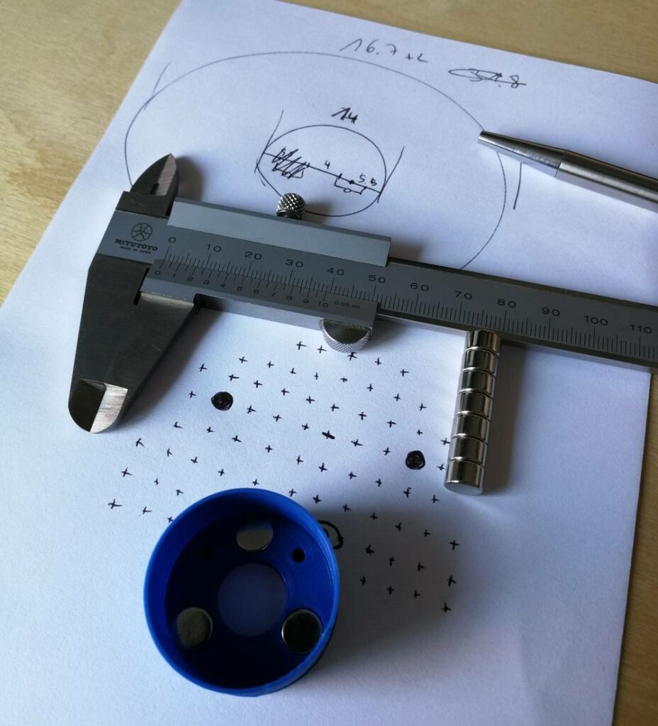
3D printed case with magnets fitted to breadboard

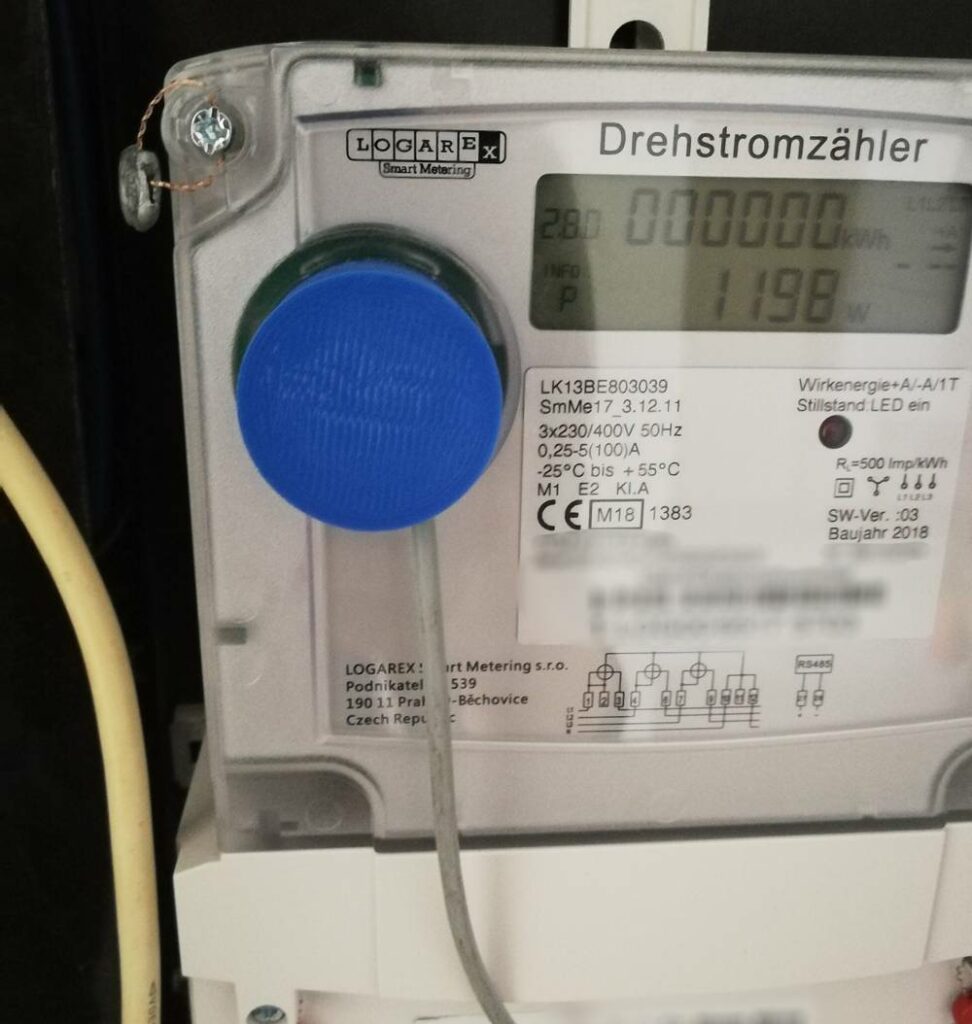
Installed meter reader head

The data is then pushed to an MQTT server and integrated in Home Assistant using the MQTT sensor component. Up to date values are now in Home Assistant and are further processed to calculate the actual current flow on every phase (load minus PV production) and used a basis for controlling the EV charging operation (more on that later).

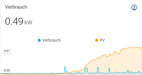
Total PV and load over time visualized with Mini Graph Card.
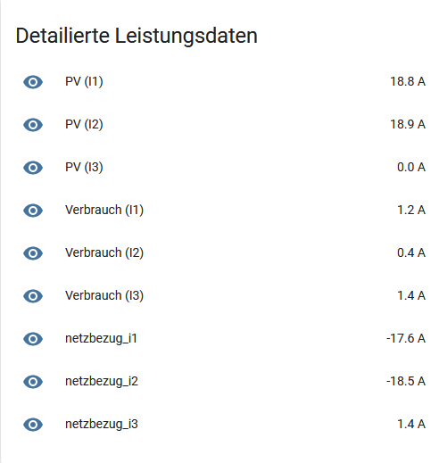
Calculated current values of all three phases.

Keba Wallbox Integration

Back then when I started with the green charging project, there was no Keba integration in Home Assistant out there (my goal was to use Home Assistant as I already have a lot of other IoT stuff managed on this plattform). Luckily the Keba wallboxes provide a UDP interface for easy monitor and control, which is well documented. So I created an integration for Home Assistant, which is finally part of the Home Assistant core starting from version 0.98 (see Home Assistant documentation) and still maintained by me. During development, reverse engineering the official BMW Wallbox app (there is a fast polling interval after sending a command to the wallbox in order to get a faster feedback on the measurement values) and following the UDP programming manual from Keba were helpful steps. If you want to use the Keba integration for your own project, now you just have to add the following configuration.

# Example configuration.yaml entry
keba:
  host: IP_OF_YOUR_KEBA_WALLBOX

Home Assistant Automations

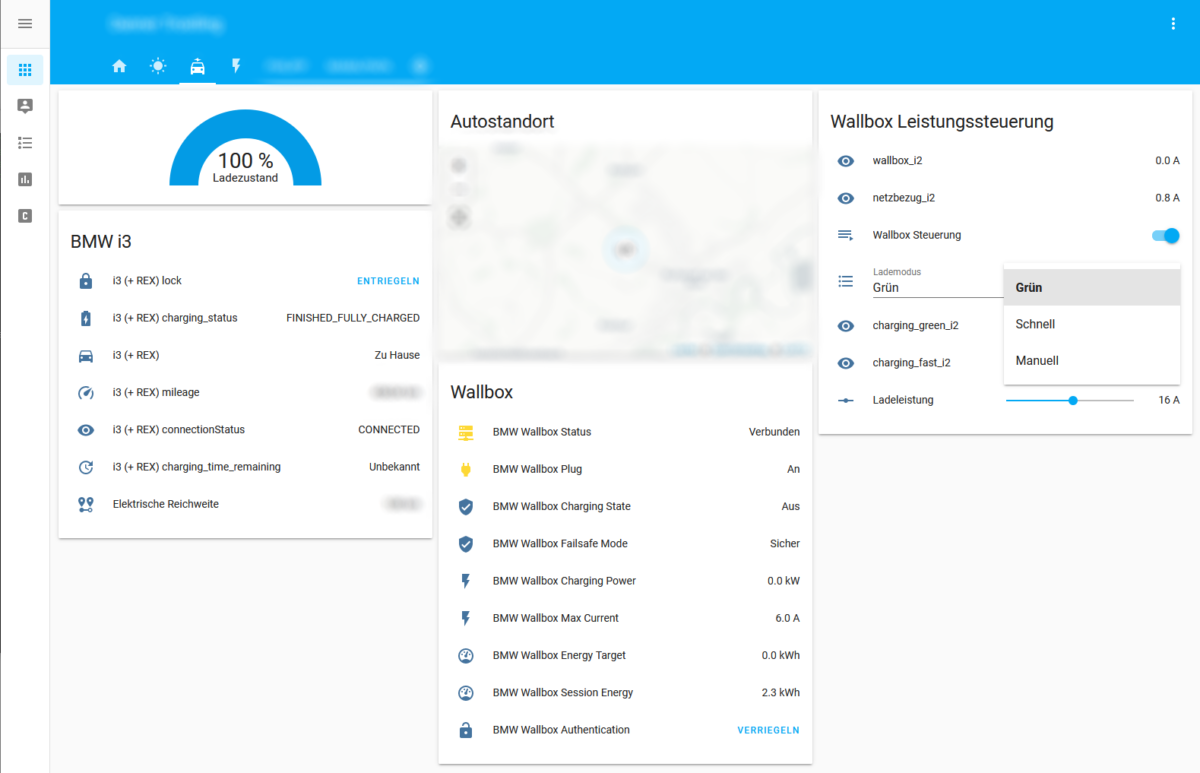
As you already can guess from the dashboard screenshot above, I have not only integrated a „green“ but actually a set of different charging modes:

  • manual: setting the charging speed (current) with a slider
  • fast: maximum charging current without breaking the fuses
  • green: charging current is the current from the PV system minus household loads but at least 6 A so that the charging process does not stop
  • extra green: same as green charging but stopping the charging process if the remaining current is below 6 A

With these four charging modes all my requirements can be satisfied. Fast charging is for limited charging time, green charging charges as green as possible but I will have a fully charged car the next morning and extra green for weekends, when I have time to split the charging process even to multiple days when the weather is not so nice.

All charging modes are implemented via a Home Assistant Automation that triggers either when the charging mode changes, the manual charging current slider is moved or the meter value changes (my BMW i3 has a single phase charger, thus only phase 2 is considered).

- id: 'XYZ'
  alias: Wallbox Control
  description: ''
  trigger:
  - entity_id: sensor.netzbezug_i2
    platform: state
  - entity_id: input_select.charging_mode
    platform: state
  - entity_id: input_number.charging_mode_manual
    platform: state
  condition: []
  action:
  - service: script.set_charging_mode

The referenced Home Assistant script (set_charging_mode) executes the keba service call using the current value depending on the selected charging mode. The current values are calculated using template sensors and are always up to date.

set_charging_mode:
  alias: Set Charging Mode
  sequence:
  - data_template:
      current: >
        {% if is_state("input_select.charging_mode", "Extragrün") -%}
          {{ states.sensor.charging_extra_green_i2.state | float }}
        {%- elif is_state("input_select.charging_mode", "Grün") -%}
          {{ states.sensor.charging_green_i2.state | float }}
        {%- elif is_state("input_select.charging_mode", "Schnell") -%}
          {{ states.sensor.charging_fast_i2.state | float }}
        {%- elif is_state("input_select.charging_mode", "Manuell") -%}
          {{ states.input_number.charging_mode_manual.state | float }}
        {%- endif %}
    service: keba.set_current

Finally one could enable the failsafe mode at the Keba Wallbox, which ensures that the charging current will be reset to a certain minimum in case there is no new update via UDP.

Test Results

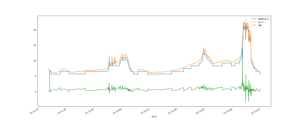
Some time ago I tested the effectiveness of the control schema on a cloudy day. In the figure below, the current from the PV (orange) and the charging current (blue) are shown. In addition, the error (green) is visualized. In this short test period, 3.412 kWh were charged, while 3.765 kWh have been produced by the PV system. Having a deeper look on the relation over time, PV overproduction of 0.356 kWh (10.43%) and underproduction of 0.003 kWh (0.009%) can be observed. This can be explained by the technical limitation that only integer ampere steps can be forwarded to the EV and that there is still a very short delay until the commands are executed. All in all, charging with 99.91% green energy is a satisfying result!

Summary

With low cost hardware (ESP32, IR sensor parts) and bunch of open source software (Arduino, Home Assistant), the Keba Wallbox is now following predefined charging modes. More than 99% of the energy in the charging process are served from the PV production in the green charging mode and blowing the main fuses is prevented. Just one question remains: How long will it take to get such a system as a product for a reasonable price for those who cannot built their own?